
NEMA Wiring Diagram Manual for Electrical Specialists
About 70% of electrical malfunctions in establishments result from inadequate wiring techniques. These figures emphasizes the necessity of following set standards, highlighting NEMA wiring diagrams’ importance for electrical professionals. Via these schematics, wiring arrangements that satisfy both performance efficiency and optimal safety criteria are presented.
The objective of this manual is to arm electrical professionals with deep understanding into NEMA criteria. Highlighting the importance of accurate electrical setups is essential. By learning these principles, specialists can drastically reduce the likelihood of incidents and ensure they meet safety standards supported by Installation Parts Supply. Expertise in l14-30 plug wiring diagram is vital whether developing modern systems or servicing present ones, as it boosts the capability to provide safe and dependable electrical answers.
Major Insights
- NEMA wiring diagrams are crucial for ensuring electrical security and compliance.
- Proper wiring practices can decrease electrical issues substantially.
- Understanding NEMA norms enhances the effectiveness of electrical setups.
- Installation Parts Supply encourages adherence to safety standards in electrical operations.
- NEMA schematics support a variety of functions across different industries.
Grasping NEMA Criteria and Their Importance
NEMA criteria are essential in the electrical sector, directing safety and operation meticulously. Crafted by the National Electrical Manufacturers Association, they set pivotal standards for creating, examining, and labeling electrical appliances. Such measures guarantee consistency and dependability across all electrical installations, which is priceless.
Identify the NEMA Criteria?
NEMA designations span from grades 1 through 13. Every level specifies the conditions necessary for electrical apparatus to operate efficiently. Such as, NEMA 1 delivers minimal indoor safeguarding but is missing dust protection. Alternatively, NEMA 4 secures devices is watertight, a necessity for enduring significant water exposure. Comprehending these classifications is key in selecting suitable equipment.
Why NEMA Norms Matter for Electrical Protection
The role of NEMA norms in guaranteeing electrical safety is profound. They are instrumental in lowering electric shock, equipment breakdowns, and fire dangers. Correct adherence to NEMA classifications empowers appliances to perform securely under specific surrounding conditions. For open-air usage, NEMA 3 classifications provide protection against the elements, safeguarding the device from inclement conditions like downpour and blizzard conditions. In regions susceptible to explosions, ratings like NEMA 7, 8, and 9 are vital for maintaining protection.
Applications of NEMA Norms in Wiring Drawings
The use of NEMA norms in wiring diagrams is crucial for protected, effective electrical installations. These diagrams make use of uniform symbols and layouts derived from NEMA standards, simplifying the interpretation of intricate electrical configurations. This uniformity is beneficial. It encourages lucidity, consistency, and reduces misinterpretations, thus improving electrical safety across domestic and industrial environments.
NEMA Wiring Schematic Fundamentals
NEMA wiring diagrams are crucial for electrical professionals, ensuring complex linkages clear. They detail the connections and components in various setups. By understanding the elements, kinds, and symbols of NEMA diagrams, electricians can boost their work in deployments and servicing.
Components of NEMA Wiring Drawings
NEMA schematics contain crucial parts for distinct electrical setups. You’ll find wiring endpoints, connectors, and additional equipment for secure linkages. Each piece secures energy is distributed effectively, in accordance with safety protocols.
Categories of NEMA Wiring Drawings
NEMA employs different schematics, like connection blueprints and electrical layouts. Such diagrams depict device relationships, while layouts show energy distribution. Choosing the appropriate diagram facilitates diagnostics and installation.
Frequent Icons Employed in NEMA Wiring Drawings
Notations in wiring schematics are essential for clear conveyance. They represent switches, loops, and connectors. Knowing these symbols aids teams interpret schematics accurately. This ensures installations meet NEMA criteria.
NEMA Wiring Diagram Characteristics
For electrical specialists, grasping the core aspects of detailed electrical wiring schematics is vital. These drawings bring both transparency and wholeness, aligning setups with NEMA criteria. They demand precise labeling and proportioning to reduce installation errors. Such practices promote a protected and optimal operational setting.
Key Features of Precise Electrical Wiring Drawings
Precise electrical wiring drawings are indispensable in electrical initiatives. They encompass important attributes such as:
- Transparency: Diagrams should be straightforward, reducing the risk of misinterpretation.
- Wholeness: They need to contain all vital elements, linkages, and electrical standards.
- Conformance: Following NEMA criteria is non-negotiable for ensuring security and operation.
- Detailed Labeling: Clear annotations on each part are fundamental for grasping and minimizing errors.
- Accurate Proportions: The scales should reflect the real setup to depict the arrangement precisely.
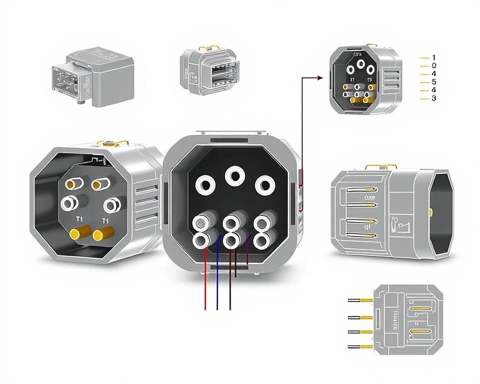
Understanding NEMA Coupler Pinout
Understanding of NEMA coupler configuration is crucial for forming accurate linkages in electrical networks. Knowledge about distinct pin setups maintains protection and device operation. There are a diversity of NEMA connectors, intended for different power levels and amperages, encompassing:
| Connector Model | Current Rating | Power Rating |
|---|---|---|
| L5-15 | 15A | 125V |
| L5-20 | 20A | 125V |
| L14-20 | 20A | 125/250V |
| L1430C | 30A | 125/250V |
| L620C | 20A | 250V |
| L1430C | 30A | 125/250V |
| L630R | 30A | 250V |
Comprehending NEMA coupler configurations is vital for secure linkages, boosting effectiveness. It’s imperative to pair connectors with equipment properly using twist-lock or linear blade variants, to prevent hazards.
NEMA Appliance Wiring
NEMA device wiring encompasses multiple configurations for safe electrical appliance interfaces. These standards confirm that equipment integrate safely, minimizing danger. Understanding the various NEMA equipment and their wiring is essential for electricians.
Different Kinds of NEMA Appliances
NEMA classifies devices by kind based on power levels and amperage needs. Essential setups are:
- 2-Pole, 2-Wire
- 2-Pole 3-Wire Grounding
- 3-Pole, 3-Wire
- 3-Pole 4-Wire Grounding
- 4-Pole, 4-Wire
- 4-Pole, 5-Wire with Grounding
These configurations are utilized in residences and manufacturing plants, supporting 125V, 208V, and 480V.
NEMA Outlet Wiring Demystified
NEMA plug wiring changes to accommodate various power needs, with locking types delivering reliable interfaces in unstable settings. For example, the L5-15 plug is rated for 15 A, frequently used in commercial locations, whereas the L14-20 is designed for 20 amps at 125/250 voltage.
The NEMA naming scheme assists in choosing the correct plugs, spotlighting features like polarity and connection to ground. This meticulousness secures that equipment function safely.
NEMA Outlet Wiring Instructions
Proper wiring of NEMA receptacles aligns with electrical regulations and safety guidelines. For example, L530R receptacles are rated for 30 amps at 125 V, with L630R models for 250 voltage. Adequate grounding is crucial to avoid electrical accidents.
Selecting approved NEMA plugs and receptacles secures safe, regulation-compliant configurations. It’s vital to refer to formal protocols when setting up.
NEMA Motor Wiring and Implementations
NEMA motor wiring is crucial in electrical engineering, especially for industrial use. Knowing how NEMA motor setup works secures that engines are installed for best performance. These motors, like single-phase and three-phase types, demand correct wiring to work safely and optimally.
Introduction of NEMA Motor Wiring
Comprehending NEMA motor wiring requires familiarity of junctions and setups. The majority of three-phase motors now support dual-voltage, indicating they can run on both low (208-230V) and high power levels (460V). Wiring at high voltage makes a motor use less current than at low voltage. High voltage advantages encompass smaller wires for the supply, a major benefit for engines exceeding 10 HP.
While both NEMA and IEC appliances are used in the industry, NEMA models are usually bigger and more expensive than IEC ones for less than 100 HP applications. NEMA starters span size 00 to 9, appropriate for diverse functions. A typical attribute in NEMA controllers is a Trip Rating of 20, engineered to trip when a motor’s draw goes beyond six times the rated current in 10 seconds.
Selecting the Correct NEMA Motor Configuration
Choosing the appropriate NEMA motor arrangement impacts system performance and protection. A common three-wire control circuit utilizes three wires for a start/stop pushbutton station, enabling simple motor operation. Typical three-phase setups include the 12 Lead Dual Voltage and 6 Lead, facilitating Wye and Delta arrangements.
IEC motor starters commonly feature phase monitoring, enhancing safety. They also offer adjustable Fault Classes for tailored protection in low voltage operations. Moreover, many models have temperature safeguards, critical for one-phase and Dual Voltage setups.
| Configuration Type | Voltage Level | Current Rating | Typical Use |
|---|---|---|---|
| 12 Lead Dual Voltage | Dual Voltage (208-230V / 460V) | Dependent on motor size | Wye Start – Delta Run applications |
| 6 Lead | Single or Dual Voltage | 32 amps maximum | Both Wye and Delta arrangements |
| Single Phase | Single-level Voltage | Varies (1-5 amps adjustment) | Dual Speed and Dual Winding setups |
| Delta Connection | High Voltage | Based on configuration | Various applications including Current Transformers |
In Summary
Grasping NEMA wiring schematics and norms is vital for electrical experts seeking to boost their expertise and adhere to electrical safety standards. These guidelines guarantee safe and effective electrical installations but also prevent risks associated with improper wiring. In summary, adhering to NEMA standards leads to the improved performance of multiple NEMA units and systems.
For electricians, the selection of quality supplies can greatly affect the success of their tasks. Installation Parts Supply offers a extensive range of wiring supplies in accordance with NEMA norms. This enables professionals to get vital elements for complying with these key requirements. Premium materials and profound expertise of NEMA wiring diagrams greatly enhance project protection and performance.
Throughout electrical setups, always place protection and exactness above all. Mastering NEMA standards offers the insight necessary for applying industry standards precisely. This guarantees that every electrical link established aligns with premium criteria.
Frequently Asked Questions
Identify NEMA wiring drawings?
NEMA wiring drawings illustrate the arrangements and linkages of NEMA-standard electrical appliances. They follow safety and performance criteria established by the National Electrical Manufacturers Association.
What makes NEMA norms crucial for electrical safety?
NEMA norms are essential to establishing safety and functional benchmarks for electrical devices. These principles assist electrical experts lower shock risks, operational errors, and fire hazards.
Which elements are essential in a NEMA wiring drawing?
Fundamental parts in a NEMA wiring drawing comprise circuit configurations and linkage diagrams. These drawings also include comprehensive markings and depict the electrical system’s diverse parts correctly for deployments.
Which kinds of NEMA wiring diagrams exist?
Diverse NEMA wiring drawings cater to various needs, including power distribution circuits and interconnection diagrams for components. Every design serves a unique role in electrical installations.
Which are the typical symbols employed in NEMA wiring drawings?
Typical symbols in these schematics represent controls, fuses, receptacles, and more. Utilization of these symbols promotes effective conveyance and precise analysis of wiring schematics.
Identify the essential attributes of accurate electrical wiring schematics?
Accuracy in electrical wiring diagrams is marked by their clarity, thoroughness, and explicit marking. They must align with NEMA norms to avoid faults in setup.
What is a NEMA connector layout?
A NEMA connector pinout describes electrical linkages at a connector, showing particular pin assignments. This secures safe and effective junctions in electrical systems.
Which are the various kinds of NEMA appliances?
NEMA units comprise various electrical outlets and interfaces, like adapters and receptacles. They are designed for various amperage and voltage specifications to satisfy particular usage needs.
In what way is NEMA plug wiring arranged?
NEMA plug wiring hinges on defined amperage and voltage levels needs, adhering to security protocols and electrical codes for multiple electrical applications.
Which standards are there for NEMA outlet wiring?
Guidelines for connecting NEMA outlets emphasize complying with electrical codes, securing correct polarity, and choosing proper wire sizes. This maintains both security and performance in electrical configurations.
What is the method to wire a NEMA motor properly?
To connect a NEMA motor, one must grasp its specific one-phase or three-phase setup. Choosing the correct wiring method is crucial, along with observing electrical safety for optimized motor performance.
What must be taken into account when selecting a NEMA motor arrangement?
Opting for a NEMA motor configuration requires an evaluation of the system’s power needs and operational characteristics. It’s also essential to verify alignment with pre-existing equipment for reliable performance and security.